In any process industry transmitters, P/E converters, Controllers, and Control valves are termed as "Process Loop Components. While using these components certain steps are required to be carried out. These steps are termed as "Connection/Configuration", "Characterisation", "Calibration", and "fault finding". In each phase the user is supposed to carry out certain tasks as per industry standard. The main unit processes which are predominantly used in industries are Temperature, Level, Pressure, and Flow control System. As per the requirement the you can select the process and follow the steps as described in the "Procedure" section. The details of each step are as follows:
- Configure a P/E converters: To configure a P/E converter you need to select type of P/E converter
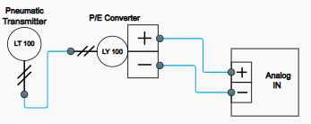
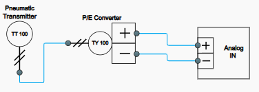
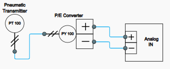
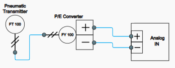
- Connection/wiring diagram: From the standard library select the components required for the connection like a power supply, P/E converters module, and an analog input card. Connect them as per standard connection diagram mentioned in theory.
- Characterisation: Once the configuration and wiring diagram is complete change the process variable and observe the output of the P/E converters. Ensure that you have exposed P/E converters to full span as far as possible take maximum readings.
- Calibration: After scrutinising the readings calculate various parameters and calibrate the P/E converters by adjusting "Zero, Span, and Linearity"
- Fault finding: In this phase a fault is introduced and the user needs to identify the fault based on the readings of the P/E converters.